DIP Switch Settings and Pin Definitions
This chapter provides guidance on setting up the DIP switch and using the internal I/Os of the Alderamin MK3 Embedded System hardware.
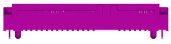
Jumper and Internal Connector Placement
Overall Layout
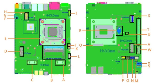
Label |
Component |
|---|---|
A |
1st Board-to-Board Connector |
B |
DIMM Sockets |
C |
2nd Board-to-Board Connector |
D |
Mini PCIe Slot 2 |
E |
CPU Socket |
F |
DIP Switch for Power COM |
G |
AT/ATX Mode Switch |
H |
M.2 Key E Connector |
I |
Board-to-Board Connector for Power Ignition |
J |
5V Power Header |
K |
5V Power Header |
L |
12V Power Header for PoE Module of Mini PCIe |
M |
12V Power Header for PoE Module of Mini PCIe |
N |
2nd SATA Signal Header |
O |
2nd SATA Power Header |
P |
FAN Header |
Q |
1st SATA Connector |
R |
Coin Battery Connector |
S |
M.2 Key M |
T |
PCIe X16 |
U |
Clear CMOS Switch |
V |
Mini PCIe Slot 1 |
W |
PCIe X1 |
X |
3rd SATA Signal Header |
Y |
3rd SATA Power Header |
DIP Switch Settings
AT/ATX Mode Selection (Location #G)
Pin Position |
Mode |
|---|---|
UP |
ATX Mode |
DOWN |
AT Mode |
Power COM DIP Switch (Location #F)
Switch Setting |
Mode |
1 |
2 |
|---|---|---|---|
COM 1 |
RI |
ON |
ON |
5V |
ON |
OFF |
|
12V |
OFF |
ON |
|
COM 2 |
RI |
ON |
ON |
5V |
ON |
OFF |
|
12V |
OFF |
ON |
Internal Connector Pin Definitions
1st SATA Connector (Location #Q)
Pin |
Signal Name |
|---|---|
P1-P3 |
VCC3 |
P4-P6 |
GND |
P7-P9 |
VCC |
P10 |
GND |
P11 |
RES |
P12 |
GND |
P13-P15 |
+12V |
S1 |
GND |
S2 |
SATAHDR_TXP0_C |
S3 |
SATAHDR_TXN0_C |
S4 |
GND |
S5 |
SATAHDR_RXN0_C |
S6 |
SATAHDR_RXP0_C |
S7 |
GND |
SATA Power Headers (Location #O/#Y - 2nd & 3rd SATA Power Headers)
Pin |
Signal Name |
|---|---|
1 |
VCC3 |
2 |
GND |
3-4 |
VCC |
5 |
GND |
6-7 |
+12V |
SATA Signal Headers (Location #N/#X - 2nd & 3rd SATA Signal Headers)
Pin |
Signal Name |
Description |
|---|---|---|
1 |
GND |
Ground |
2 |
SATAHDR_TXP_C |
SATA Data Transmit (Positive) |
3 |
SATAHDR_TXN_C |
SATA Data Transmit (Negative) |
4 |
GND |
Ground |
5 |
SATAHDR_RXN_C |
SATA Data Receive (Negative) |
6 |
SATAHDR_RXP_C |
SATA Data Receive (Positive) |
7 |
GND |
Ground |
Fan Header (Location #P)
Pin |
Signal |
|---|---|
1 |
Ground |
2 |
+12V |
3 |
CPU_FAN_TACH |
4 |
CPU_FAN_CTRL |
M.2 Connectors
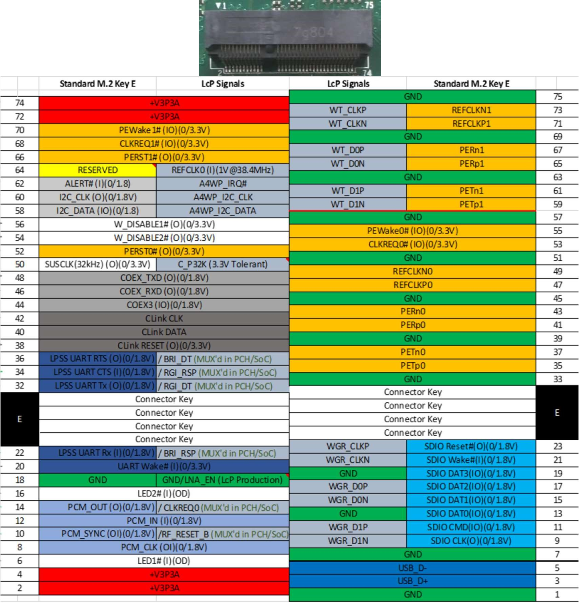
M.2 Key E Slot (Location #H)
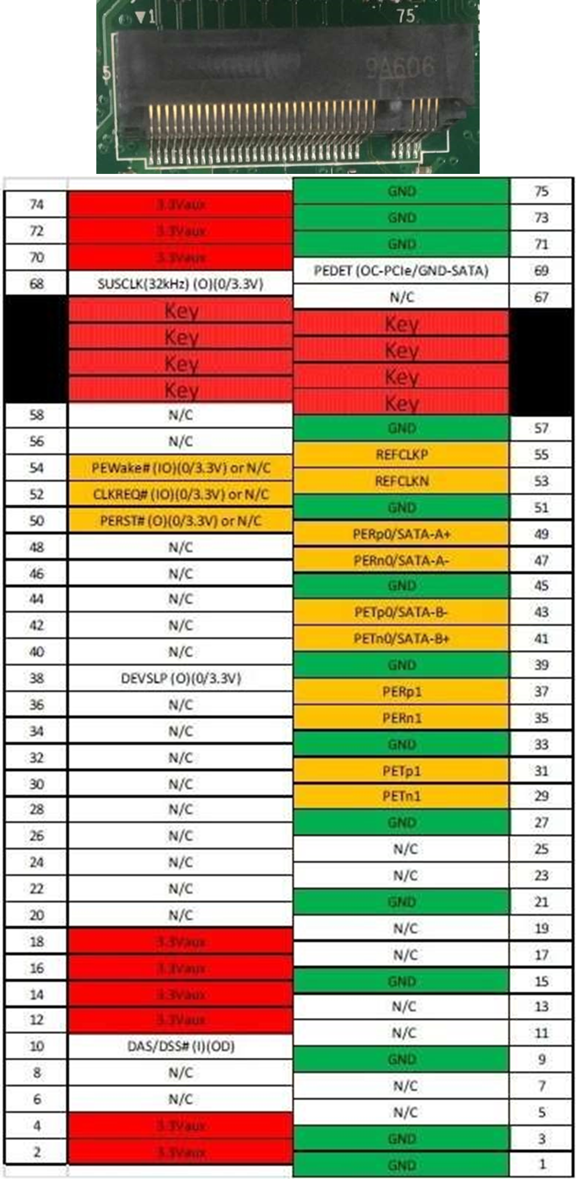
M.2 Key M Slot (Location #S)
12V Power Headers for PoE Xpansion (Location #L/#M)
Pin |
Signal |
|---|---|
1 |
Ground |
2-3 |
+12V |
4 |
GND |
5V Power Headers (Location #J/#K)
Pin |
Signal |
|---|---|
1 |
+5V |
2 |
Ground |
External Connector Pin Definitions
3-Pin Terminal Block for DC Input
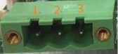
Pin |
Signal |
|---|---|
1 |
DC IN +9~48VIN |
2 |
Ignition (IGN) |
3 |
GND |
4-Pin Terminal Block for PWM Fan
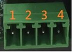
Pin |
Signal |
|---|---|
1 |
Ground |
2 |
+12V |
3 |
System_FAN_TACH |
4 |
SYSTEM_FAN_CTRL |
2-Pin Terminal Block for Remote Power ON/OFF and Reset
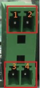
Pin |
Signal |
|---|---|
1 |
Ground |
2 |
EXT Reset |
3 |
Ground |
4 |
EXT_PWRBT_ON/OFF |
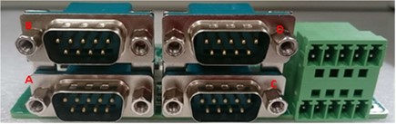
Expansion Modules
COM/DIO Expansion Module
This module consists of Serial COM and Digital IO functions.
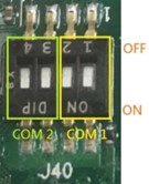
COM Port Settings
Location: Supports 4 COM ports (Configurable as RS232/RS485/RS422).
DIP Switch Functions
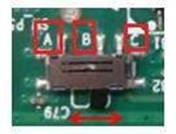
COM ID Selection Switch
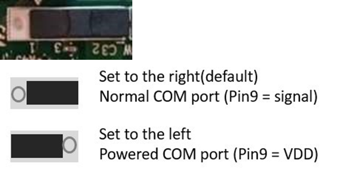
Powered COM Enable Switch
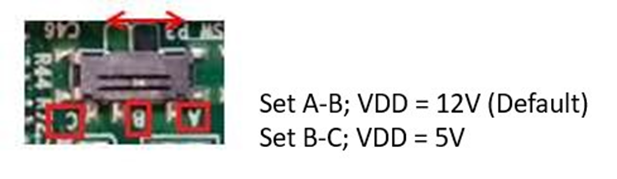
Powered COM Power Source Selection Switch
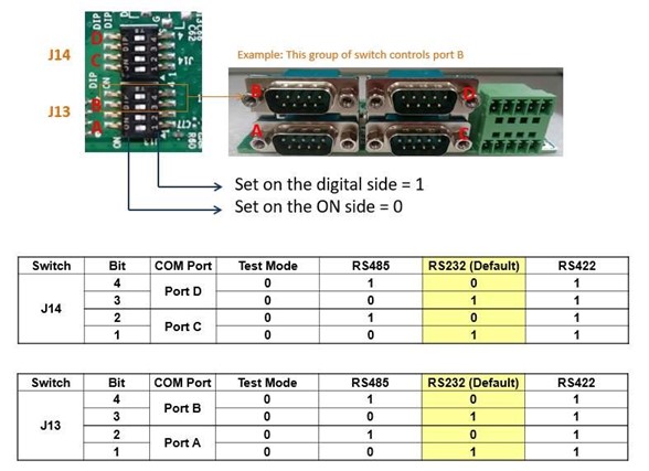
COM Mode Setting Switch
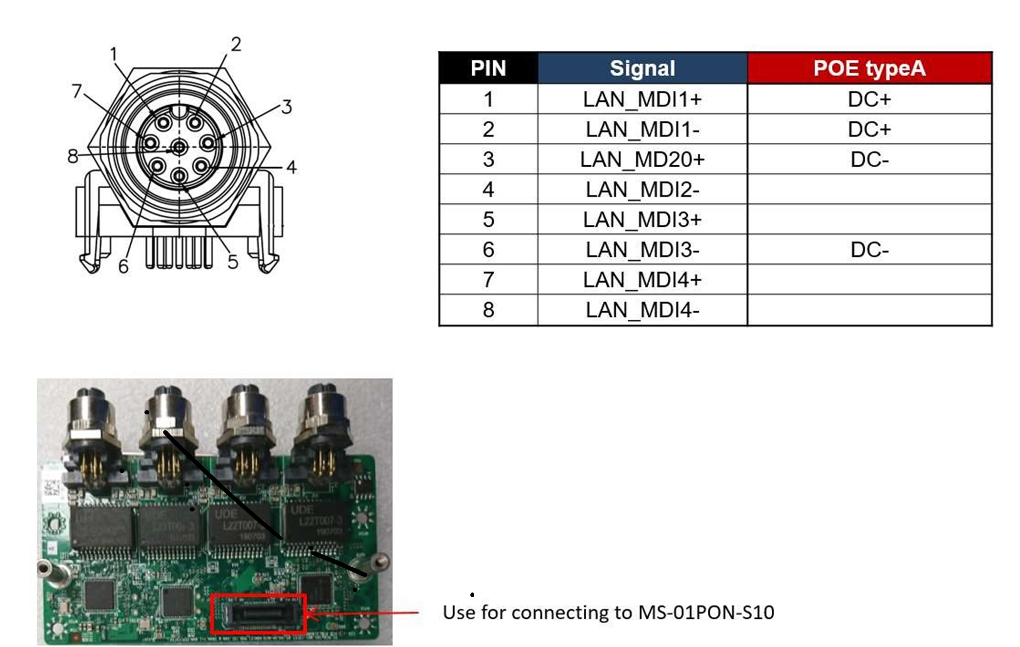
LAN Expansion Module
Supports four M12 type interfaces for Giga LAN connectivity.
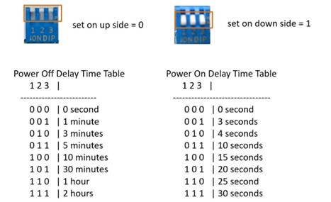
Ignition Expansion Module
Detects vehicle ignition status and controls power delay settings.
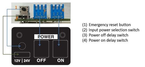
Delay Power On/Off Setting Switch