System Setup
This chapter provides guidance on setting up the Alderamin MK3 Embedded System hardware.
⚠️ Warning: The edges of the ALDERAMIN MK3 aluminum extrusion fins are sharp. Handle the unit carefully during installation, movement, and operation.
2.5” SATA HDD/SSD Installation
Follow these steps to install a SATA HDD:
Remove the door from the front bezel.
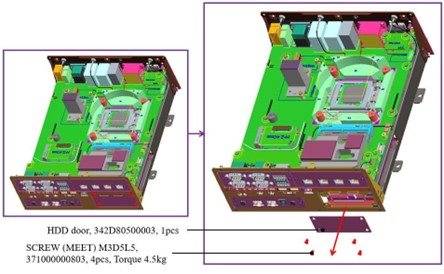
Note: Loosen the four screws from the expansion door, then gently lift the cover with your fingernail to carefully remove it.
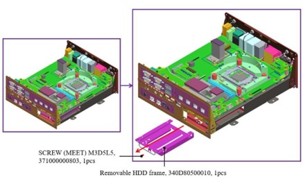
Pull the HDD tray out from the main chassis.
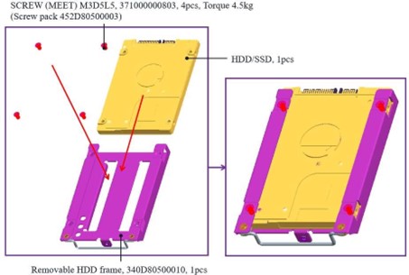
Secure the HDD/SSD to the bracket using screws.
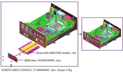
Insert the HDD/SSD tray back into the main chassis and fasten the screws on the door.
Note: Keep the unit horizontal to facilitate smooth reinsertion of the HDD tray.
2nd and 3rd 2.5” SATA HDD/SSD Installation
Remove the GND screws from the rear bezel.
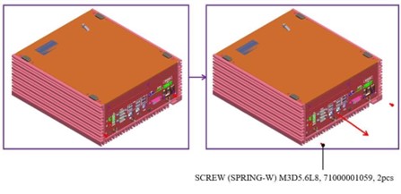
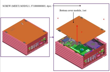
Remove the bottom cover.
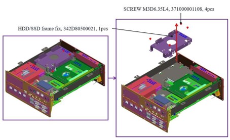
Loosen the four HDD bracket screws and pull the bracket out of the unit.
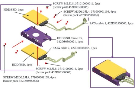
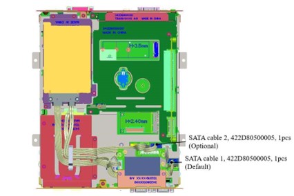
Secure the 2nd and 3rd HDD/SSD to the bracket as illustrated in the concept drawing.
Fasten the four bracket screws to the main unit.
Follow the guide for proper SATA cable routing.
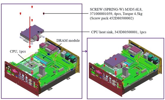
CPU, CPU Heatsink, and DRAM Installation
Remove the GND screws from the rear bezel.
Remove the bottom cover.
Loosen the four M4 screws from the main chassis.
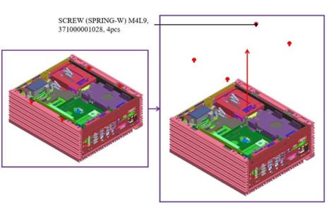
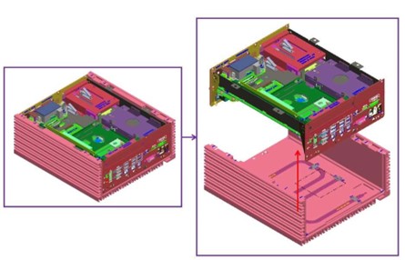
Ensure the two GND screws are loosened, then carefully pull the main chassis from the aluminum extrusion.
The aluminum extrusion has chipset thermal pads (L6) and two guide pins, so some force may be required.
Warning: The aluminum and metal edges are sharp—handle with extreme caution when pulling the main chassis out.
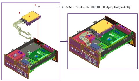
Take the CPU passive cooler from the accessories and install the CPU, CPU heatsink, and DRAM modules as shown.
RTC Battery Maintenance
Preparation for Disassembly
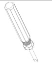
Flathead Screwdriver (Required for battery removal due to high vibration resistance design)
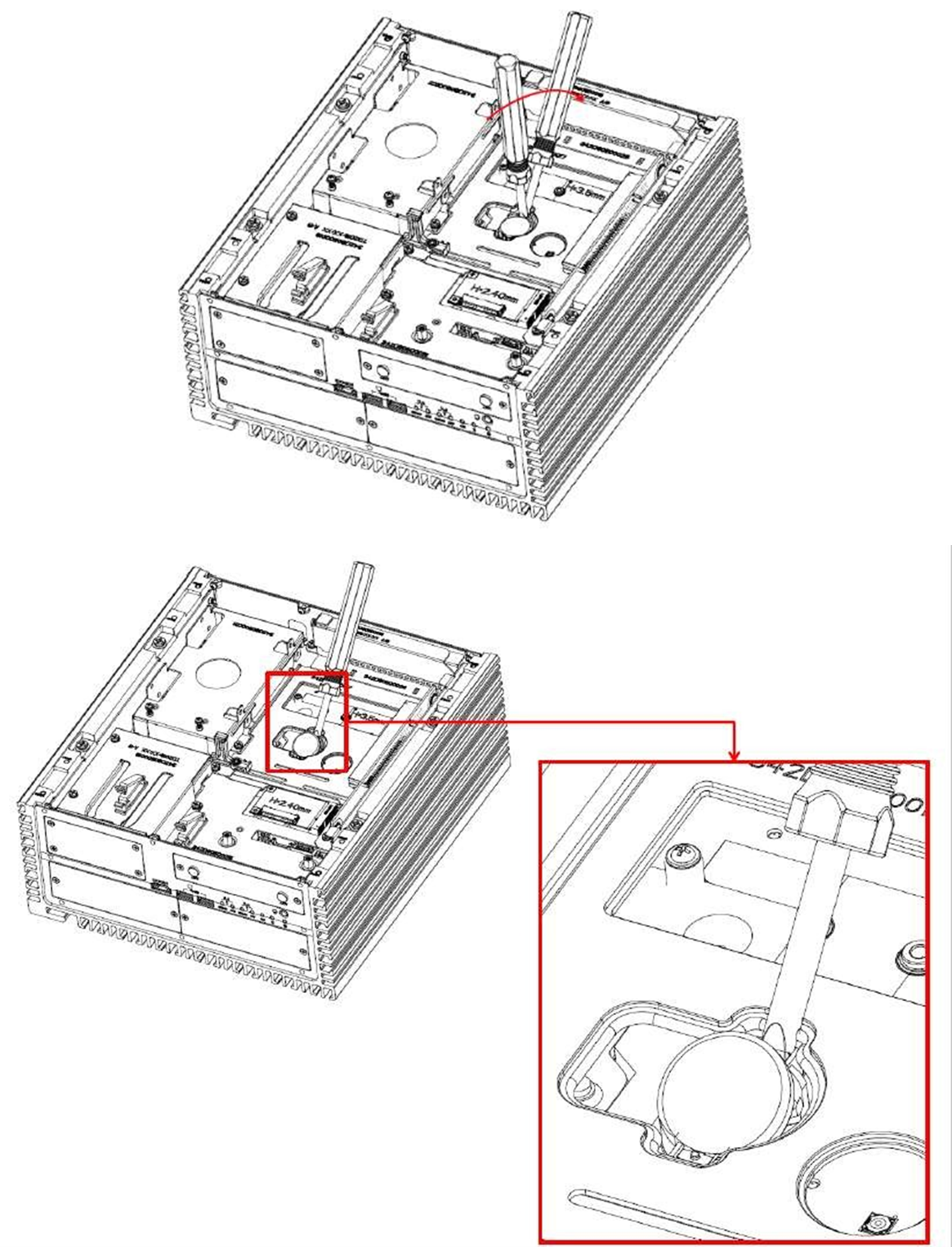
Insert the flathead screwdriver into the gap on one side of the RTC battery vertically.
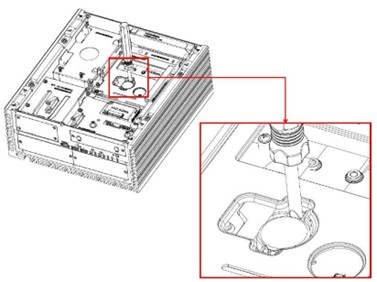
Rotate the screwdriver about 45 degrees to loosen and remove the coin battery.
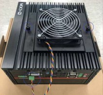
External Fan (Optional) Installation Guide
Twist the thumbscrews counterclockwise on the external fan.
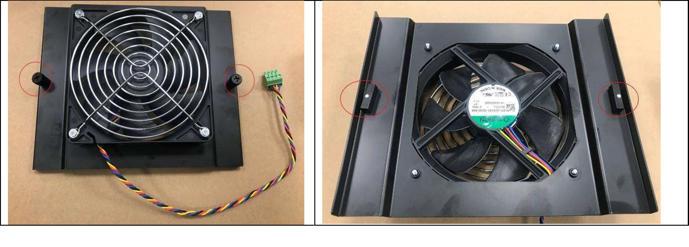
Align the edge of the external fan bracket with the green arrows and align the metal latch with the red arrow direction.
Insert the fan into the center of the housing.
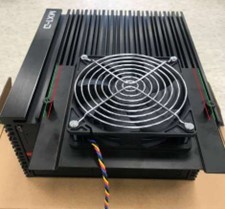
Tighten the thumbscrews to secure the external fan and connect the 4-pin cable to the PWM fan connector on the rear I/O.
Note: Do not operate the system when it is powered on. Improper installation of the external system fan while the system is running may cause injury.